Swiss-type CNC lathes occupy a fairly specific niche in precision turning, one that’s basically defined by the problem they solve. Conventional lathes struggle—seriously struggle—when workpiece diameter drops below roughly 12mm and part length pushes the aspect ratio past 4:1. Deflection, chatter, dimensional drift. The result? Scrapped parts and tight tolerances that simply aren’t achievable.
Swiss-type machines address this through a fundamentally different support architecture. And the downstream effects touch everything: tolerance capability, material selection, cycle economics, and viable part geometry. This article covers the core technical parameters across each of those areas—written for engineers specifying parts, essentially, what you need to know before you send the drawing.
How Swiss-Type Architecture Differs from Conventional Turning
The Cantilever Problem
In conventional turning, the workpiece is gripped at the chuck and extends outward—unsupported. Think of it like a cantilever beam, fixed at one end, free at the other. At aspect ratios (length-to-diameter, or L/D) beyond roughly 4:1, the physics get ugly. Cutting forces create deflection at the free end, and that deflection shows up as dimensional error. Tighter tolerances just make the problem more visible.
Proximity Support Principle
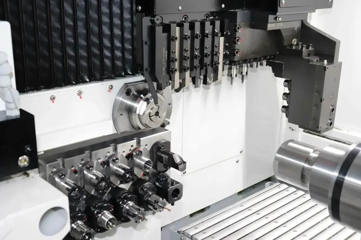
Swiss-type machines use a guide bushing (a precision sleeve supporting the workpiece at or very near the cutting zone) to eliminate that cantilever condition entirely. The bushing sits typically 1–3mm from the active cutting tool. So no matter how long the part eventually becomes, the supported length at any given moment stays constant. Practically speaking, L/D ratios of 20:1 are routine—sometimes higher, within certain constraints.
Motion Inversion
Here’s where it gets conceptually different. In conventional turning, the tool carriage moves along a stationary workpiece. Swiss-type machines invert this: the headstock (with the spindle and stock material) translates axially, feeding the workpiece through the stationary guide bushing toward the tools. The tools essentially work in a fixed zone. It’s a subtle difference architecturally, but it’s why the whole support principle works.
Tolerance Capabilities and Material Constraints
Dimensional Precision Ranges
Standard Swiss-type turning handles bar stock from roughly 0.1mm up to about 32mm diameter, depending on machine class. Under production conditions—stable thermal environment, properly conditioned tooling—diameter tolerances of ±0.005mm are essentially routine. Surface finish typically falls in the Ra 0.2–0.4μm range for turned surfaces in steel or brass; harder materials and interrupted cuts tend toward the rougher end of that band.
Tighter tolerances, say ±0.002mm or better, are achievable but require process controls that go beyond standard setup. More on that in the thermal section below.
Material Suitability Matrix
Not all materials behave equally in Swiss turning. This is where a lot of DFM (design for manufacturability) errors happen—specifying a material that’s technically machinable but problematic at small diameters and tight tolerances.
316L stainless (medical grade, ASTM F138) is essentially the benchmark material for Swiss-type work in the medical device space. It machines predictably, holds tolerances well, and is corrosion-resistant. Aluminum 7075 is excellent for electronics and aerospace connector applications—lighter, faster cycle times, but thermally sensitive in ways that matter (discussed below). Titanium Ti-6Al-4V, the implant-grade alloy, is a different beast. Work-hardening behavior means tool life degrades quickly if parameters aren’t managed. Brass alloys (C36000 and similar) are probably the easiest to machine in this format—good chip control, decent surface finish, not thermally fussy.
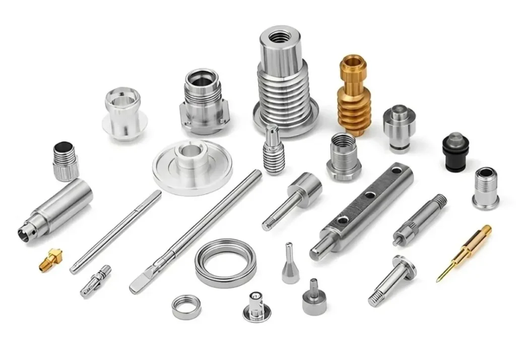
Table 1: Material Suitability for Swiss-Type CNC Turning
| Material | Standard Tolerance Limit | Max Practical L/D | Typical Industry Application |
| 316L Stainless (ASTM F138) | ±0.005mm | Up to 20:1 | Medical implants, surgical tools |
| Titanium Ti-6Al-4V | ±0.008mm | Up to 15:1 | Orthopedic implants, aerospace fasteners |
| Aluminum 7075 | ±0.005mm | Up to 20:1 | Electronics connectors, sensor housings |
| Brass C36000 | ±0.003mm | Up to 25:1 | Fluid fittings, electrical contacts |
| 17-4 PH Stainless | ±0.006mm | Up to 18:1 | Aerospace components, precision shafts |
Thermal and Environmental Factors
This section gets underappreciated. Basically, the thermal expansion stuff gets complicated, whatever you want to call it—and at ±0.005mm tolerances, temperature swings that seem minor actually aren’t.
For steel, the thermal expansion coefficient runs around 11–12 μm/m·°C. When the thermal expansion coefficient of roughly 11.7μm/m·°C interacts with a 4°C gradient observed across a machine’s bearing span during a standard production run, the resulting dimensional drift becomes measurable at roughly 0.006mm give or take. That’s your entire tolerance band. Gone.
Aluminum is worse—coefficient around 23μm/m·°C, meaning an ambient temperature shift of 5°C can introduce approximately 0.003mm of part expansion on a 25mm feature. The 85% relative humidity threshold is generally cited as the practical upper limit for aluminum work in production environments; above that, condensation-related effects on coolant mixing ratios and workpiece handling become variables.
Coolant pressure matters here—reminds me of a hydraulic line pressure drop situation on a completely different machine actually, but the principle is similar—and should stay between 40–70 bar for effective chip evacuation and thermal management in Swiss-type turning. Higher pressure can affect guide bushing clearance dynamics in some configurations.
So. Short version: ±0.005mm capability requires ±2°C thermal stability. That’s the tolerance band we’re working with.
Geometric Constraints
Wall thickness minimums sit around 0.05mm for thin-wall tubular features—below that, deflection during the cut introduces errors that are basically impossible to compensate for. Feature proximity rules generally require spacing of at least 0.3mm between adjacent turned features to allow tool clearance. And interruptions—grooves, cross-holes, flats—in the guide bushing support zone create vibration that telegraphs directly into dimensional error. That’s not always avoidable, but it needs to be accounted for in setup.
Design Parameters for Production Viability
DFM Guidelines
Entry chamfers. Non-negotiable. Parts entering the guide sleeve need a lead-in—typically 15–30° chamfer—to prevent scoring the bushing bore. Wall thickness transitions should hold roughly a 3:1 ratio maximum (gradual taper rather than abrupt shoulder where possible), which helps maintain consistent cutting forces through the transition. And hex flats, knurling, or other non-cylindrical features in the bushing support zone are problematic—they create clearance gaps that allow micro-movement during the cut.
Actually, that last point is worth clarifying. Or rather, it’s not that hex features can’t be produced at all—it’s that they should be located outside the bushing support zone wherever design allows.
Tolerance Stacking
Setup variation—the dimensional shift between fixturing, re-chucking after barstock changes, and tool offset drift—typically contributes ±0.003mm to part-to-part variation under normal conditions. Batch-to-batch consistency adds another variable layer if incoming material diameter varies more than ±0.01mm (which some bar stock suppliers allow). Measurement uncertainty propagation from CMM (coordinate measuring machine) verification adds roughly ±0.001mm at 2-sigma confidence. So the practical achievable tolerance in production, accounting for all these stacked sources, generally resolves to ±0.008–0.010mm unless process controls specifically target the tighter end.
Economic Thresholds
Setup amortization for Swiss-type jobs starts making sense somewhere above 500 pieces, generally. Below that, setup cost per part becomes difficult to justify—competing processes like precision grinding or even wire EDM may be more economical for small quantities. Cycle times range roughly 30–120 seconds per part depending on complexity and number of operations (Swiss machines frequently complete multiple operations—turning, drilling, threading—in a single setup). Cost-per-piece drivers are tool life, bar stock utilization, and cycle time, in roughly that order of impact.
Applications by Industry Sector
Medical Devices
This is sort of the canonical application for Swiss-type turning—catheter components, guidewires, bone screws, dental implant posts. The combination of small diameter, high L/D, and tight tolerances describes basically every implantable component. ISO 13485 quality system requirements and ASTM F138 material compliance for 316L stainless are standard baseline requirements for suppliers in this space. Wall thickness on catheter tube components routinely reaches 0.1–0.2mm, which is essentially the practical limit for this process.
Aerospace Components
Sensor housings, connector pins, valve components. AS9100 compliance is the quality standard that matters. Tolerances in aerospace connector applications typically run ±0.005–0.008mm, and material traceability requirements are stricter than most other industries—meaning documentation of material heat lot, processing history, and inspection records accompanies every production run. Titanium use is common here, with all the tool life implications that come with it.
Electronics Manufacturing
Micro-connectors, sensor probe elements, precision shafts for miniaturized mechanisms. Diameter pins down to 0.2mm are produced routinely on Swiss-type machines with appropriate tooling. Aluminum 7075 dominates this segment for weight reasons. But the thermal sensitivity noted earlier means electronics-sector Swiss work is typically done in climate-controlled production environments.
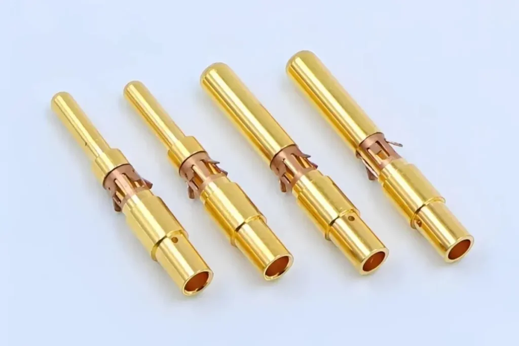
Table 2: Industry Application Summary
| Industry | Typical Material | Tolerance Class | Quality Standard |
| Medical Devices | 316L SS (ASTM F138) | ±0.005mm | ISO 13485 |
| Aerospace | Ti-6Al-4V, 17-4 PH | ±0.008mm | AS9100 |
| Electronics | Aluminum 7075, Brass | ±0.005mm | IPC-A-610 |
| Fluid Systems | Brass C36000, 316L SS | ±0.010mm | ASTM B16.26 |
Process Limitations and Alternative Methods
Batch Size Economics
Below roughly 200 pieces, setup amortization math gets difficult for Swiss-type work. Precision grinding—particularly centerless grinding for cylindrical features—offers ±0.001mm capability and often lower setup complexity for simple geometries. For complex multi-feature parts at low quantity, wire EDM (electrical discharge machining, which cuts complex profiles using a fine wire electrode) provides geometric flexibility Swiss turning can’t match, at comparable or better precision.
Geometric Impossibilities
Internal threads below M1.0 (1mm pitch diameter) push past what standard Swiss threading attachments handle reliably. The thread form geometry at that scale, combined with chip clearance, creates tool engagement problems. Extreme L/D ratios above approximately 30:1 also move outside viable range—even with guide bushing support, barstock feeding stability and vibration become unmanageable for most production setups. And internal bores below roughly 0.3mm diameter with L/D greater than 5:1 are basically off the table.
Alternative Processes
Wire EDM handles complex 2D profiles at ±0.002–0.003mm. Precision cylindrical grinding reaches ±0.001mm on outside diameters with excellent surface finish. And for prototyping or very low quantities, metal additive manufacturing—specifically laser powder bed fusion—can produce near-net shapes that require only final grinding or turning to reach tolerance. Not a substitute for Swiss turning in production, but worth knowing as a prototyping path.
Conclusion
The bottom line is this: Swiss-type CNC turning is essentially a geometry-driven decision. If the part diameter is under 12mm and the L/D exceeds 4:1 at tight tolerances, this process is usually the right answer. If it doesn’t meet those criteria, it might still be viable—but the economics shift.
Before finalizing a Swiss-type specification, one thing worth validating: confirm the critical tolerance features are located outside the guide bushing zone or are otherwise compatible with the proximity support principle. That single check catches a surprising number of DFM issues before tooling gets cut.
And the thermal sensitivity stuff is underestimated more often than not. If you’re working through tolerance stack-up on a tight-tolerance Swiss component—especially in aluminum or thin-wall stainless—[the DFM reference charts for Swiss-type turning] are worth bookmarking before the drawing goes out for quote.