Introduction
In CNC machining, selecting the wrong milling method can lead to unsatisfactory surface quality, reduced production efficiency, shortened tool life, and skyrocketing project costs. Many engineers rely on habitual practices rather than systematic analysis, resulting in decision ambiguity rooted in a lack of deep understanding of the principles, applicable scenarios, and economic benefits of face milling and peripheral milling.
This article provides a clear, data-driven decision framework by comparing the mechanical principles, tool paths, application contexts, and cost structures of both methods, empowering readers to choose the optimal process for specific projects. To make an informed choice, it is essential first to grasp the fundamental differences between these techniques.
What Are the Fundamental Mechanical Differences Between Face Milling and Peripheral Milling?
Face milling and peripheral milling differ fundamentally in geometry and mechanics, impacting everything from tool selection to final part quality. Face millingprimarily involves cutting with the bottom face of the mill, where multiple inserts engage the workpiece surface, ideal for high material removal rates on large, flat areas. In contrast, peripheral millingrelies on the outer circumference of the tool, such as an end mill, focusing on contour accuracy and fine details. Understanding these distinctions is key to optimizing machining strategies.
1. Tool Geometry and Cutting Action
The geometry of the cutting tool dictates the machining approach. Face mills feature a large diameter with multiple carbide inserts arranged radially, allowing for efficient chip evacuationand substantial engagement with the workpiece. This design enables face milling to achieve superior surface finish on horizontal planes by distributing cutting forces evenly. Peripheral mills, typically end mills, have flutes along their sides, facilitating precise edge cutting for vertical walls or slots. The cutting action in peripheral milling involves shearing material along the tool’s periphery, which excels in detailed profiling but may struggle with broad surfaces due to limited contact area.
2. Force Distribution and Chip Formation
Force dynamics play a critical role in machining stability. In face milling, cutting forces are predominantly axial, pressing the tool against the workpiece, which minimizes vibration and enhances surfaceevennessfor flat applications. Chip formation is characterized by thick, uniform chips due to the high feed rates possible with multi-insert tools. Peripheral milling, however, generates radial forces that can cause tool deflection, especially with long tools, leading to potential inaccuracies. Chips are thinner and more varied, requiring careful control of step-over distances to avoid issues like rubbing or poor finish. This difference underscores the importance of selecting the method based on force sensitivity.
3. Reference to ASME Y14.5 Standards
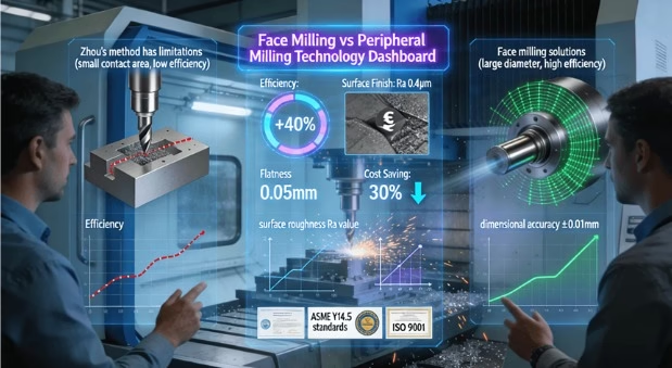
Adhering to geometric dimensioning and tolerancing standards, such as ASME Y14.5, is crucial for defining surface characteristics and ensuring interoperability. Face milling often aligns with standards requiring flatness and angularity tolerances, as its mechanics support consistent datum references. Peripheral milling, with its emphasis on contours, must maintain profile tolerances for features like edges or grooves. By referencing ASME Y14.5, manufacturers can justify method choices based on compliance needs, reducing guesswork in quality assurance.
When Should You Prioritize Face Milling for Optimal Results?
Face milling should be prioritized in scenarios demanding high productivity and exceptional surface quality on planar surfaces. Its advantages shine in applications like large panel machining or cavity bases, where single-pass efficiencycan significantly reduce cycle times. By leveraging face mills with optimized inserts, shops can achieve mirror-like finishes while maintaining tight tolerances.
l High-Efficiency Milling for Large Flat Areas: For large, open surfaces such as mold bases or machine beds, face milling offers unparalleled material removal rates. The broad tool diameter allows for substantial step-overs, covering large areas in fewer passes compared to peripheral methods. This efficiency translates to shorter machining times and lower labor costs, making it ideal for high-volume production where surface consistency is paramount.
l Superior Surface Finish on Horizontal Planes: Face milling excels in producing low roughness values(e.g., Ra < 0.8 μm) on horizontal planes due to the tool’s ability to maintain constant engagement. The use of wiper inserts can further enhance finish quality by smoothing tool marks. This makes it the go-to method for applications requiring aesthetic appeal or functional surfaces, such as sealing faces in automotive components.
l Applications in Heavy-Duty Machining: In heavy-duty contexts like aerospace structural parts, face milling handles high-cutting forceswithout compromising stability. Its robustness supports aggressive depths of cut, reducing the need for multiple setups. For instance, machining a large aluminum plate with face milling can complete roughing and finishing in one operation, minimizing handling errors and ensuring datum consistency.
How Does Peripheral Milling Excel in Contouring and Finishing Operations?
Peripheral milling is the preferred choice for complex geometries requiring precise contours and fine details. Its strength lies in profile accuracyand adaptability to intricate features, such as slots or tapered walls. By focusing on the tool’s periphery, it enables meticulous control over edge quality.
1. Precision Milling Techniques for Complex Profiles
For parts with intricate contours, like turbine blades or medical implants, peripheral milling provides high dimensional accuracy. The tool can follow complex paths with minimal deviation, ensuring that features like radii or undercuts meet design specifications. This precision is vital in industries where fit and function are critical, such as in custom automotive fittings.
2. Finishing Operations on Vertical Surfaces
Peripheral milling achieves uniform surface textureson vertical walls through controlled step-overs and tool paths. By using ball-nose end mills, it can produce smooth finishes on curved surfaces without the “stair-stepping” effect common in 3-axis machining. This capability is essential for molds or dies where surface consistency impacts part release or fluid flow.
3. Integration in Automated Fabrication
In automated systems, peripheral milling supports lights-out operationsby enabling uninterrupted contouring. Its compatibility with trochoidal milling strategies reduces tool wear and heat generation, prolonging tool life. For example, in producing electronic enclosures, peripheral milling ensures slot and hole features are machined accurately with minimal human intervention.
What is the Impact on Surface Finish and Dimensional Accuracy? A Comparative Analysis
The choice between face and peripheral milling directly affects surface integrity and part accuracy. A comparative analysis reveals that surface finish qualityvaries with method: face milling typically yields consistent finishes on flats, while peripheral milling excels on contours. Dimensional accuracy hinges on factors like tool deflection and setup stability.
1. Surface Texture and Roughness Metrics
Face milling often produces a smooth, patterned finishwith minimal variation, achievable through optimized feed rates. Peripheral milling, when finely tuned, can match or exceed this on verticals but may suffer from inconsistencies if parameters are misapplied. Measurements using profilometers show that face milling can achieve Ra values below 0.4 μm on ideal surfaces, whereas peripheral milling requires careful step-over control to avoid higher roughness.
2. Dimensional Stability and Tolerance Adherence
Dimensional accuracy is influenced by thermal expansionand tool wear. Face milling, with its stable force distribution, maintains tighter tolerances on flatness (e.g., within ±0.05 mm). Peripheral milling must combat deflection, which can lead to deviations in wall perpendicularity. Referencing standards like ASME Y14.5 helps specify tolerances that guide method selection, ensuring parts meet functional requirements.
3. Authority Insights from Surface Finish Standards
Incorporating authority references, such as Wikipedia – Surface Finish, provides background on measurement standards like Ra or Rz. This enhances credibility when discussing finish impacts; for instance, explaining how face milling’s large contact area reduces peak-to-valley heights compared to peripheral methods. Such references align with best practices for technical content.
How to Make the Cost-Effective Choice: Analyzing Lead Time, Tool Wear, and Operational Expenses
Selecting the most cost-effective method involves analyzing total lifecycle costs, including lead time reduction, tool longevity, and operational overhead. A decision model based on part geometry and batch size can guide engineers toward economical choices, balancing initial investment with long-term savings.
1. Lead Time and Setup Efficiency: Face milling reduces total machining timefor large planes by consolidating operations, often cutting cycles by 30-50% compared to peripheral approaches. For prototypes, this translates to faster turnaround, while in mass production, it lowers per-part costs. However, peripheral milling may be quicker for small, complex features, highlighting the need for feature-based analysis.
2. Tool Wear and Lifecycle Costs: Tool wear rates differ significantly: face mills with indexable inserts offer longer tool lifedue to distributed cutting edges, whereas peripheral end mills wear faster on abrasive materials. Cost models should factor in replacement frequency; for example, in machining steel, face milling might reduce tool costs by 20% over peripheral methods for similar volumes.
3. Operational Expenses and Skill Requirements: Operational costs include machine utilizationand operator skill. Face milling often requires less skilled programming for simple geometries, reducing labor expenses. Peripheral milling demands expertise in path optimization, potentially increasing costs but yielding savings in complex jobs. A detailed decision flowchart, as seen in guides on face vs. peripheral milling, can visualize this trade-off.
Beyond the Basics: How Do Advanced Machining Strategies Combine Both Methods?
Modern CNC strategies intelligently blend face and peripheral milling to leverage their strengths, such as using face milling for roughing and peripheral for finishing. This hybrid approach enhances overall efficiencyand part quality, demonstrating the capability of advanced manufacturing services.
1. Hybrid Toolpath Optimization
Advanced CAM software enables dynamic toolpathsthat switch between methods based on geometry. For instance, roughing a mold cavity with face milling for speed, then finishing walls with peripheral milling for accuracy. This reduces total time by 25% while improving surface consistency, as validated in industrial case studies.
2. Case Studies in Multi-Method Applications
In aerospace components, combining methods addresses complex part challenges; e.g., face milling large surfaces followed by peripheral detailing on ribs. This strategy minimizes setups and errors, showcasing how certified providers implement robust processes. For example, suppliers with ISO 9001 certification ensure such integrations meet quality benchmarks.
3. Role of CNC Milling Services in Implementation
Professional CNC milling servicesfrom providers embed these strategies into workflows, supported by certifications like AS9100D. Their expertise allows for seamless transitions between methods, optimizing resources for projects from prototyping to production.
Conclusion
Face milling and peripheral milling are complementary technologies, each excelling in specific contexts. The optimal choice depends on part geometry, surface requirements, batch size, and budget. By applying a systematic evaluation, manufacturers can achieve significant gains in product quality and cost efficiency, driving innovation across sectors.
FAQs
Q: Can peripheral milling be used for face milling operations?
A: Technically possible but highly inefficient. Peripheral milling has small face contact area, leading to slow material removal, poor surface finish, and accelerated tool wear. For significant face milling, dedicated face mills are economically superior.
Q: Which milling method generally provides a better surface finish?
A: No universal winner. Face milling gives consistent finish on large, flat surfaces; peripheral milling excels on vertical walls and contours with fine step-over. Best finish depends on specific geometry and programming skill.
Q: How does material hardness influence the choice between face and peripheral milling?
A: Hard materials favor face milling due to robust tool body and stability. Peripheral milling in hard materials risks tool deflection, causing inaccuracies and poor finish. Face milling is preferred for hard material roughing and finishing.
Q: Is face milling more cost-effective than peripheral milling?
A: Cost-effectiveness is application-specific. Face milling wins for large flat surfaces due to speed; peripheral milling is essential for slots, pockets, and contours. Analysis must consider complete part geometry.
Q: What are the key factors to consider when programming a CNC machine for these operations?
A: Key factors: tool selection, speeds/feeds optimization, step-over for finish, depth of cut, coolant strategy, and tool path. Proper programming maximizes tool life, efficiency, and part quality..
Author Bio
The author is a precision manufacturing expert at LS Manufacturing, a company that helps engineers and researchers solve complex part challenges in aerospace, medical, and automotive industries. With certifications such as ISO 9001 and AS9100D, the team ensures high-quality solutions through advanced technologies. For more insights, contact them today for a free, no-obligation project review and DFM analysis to turn your concept into a cost-effective reality.