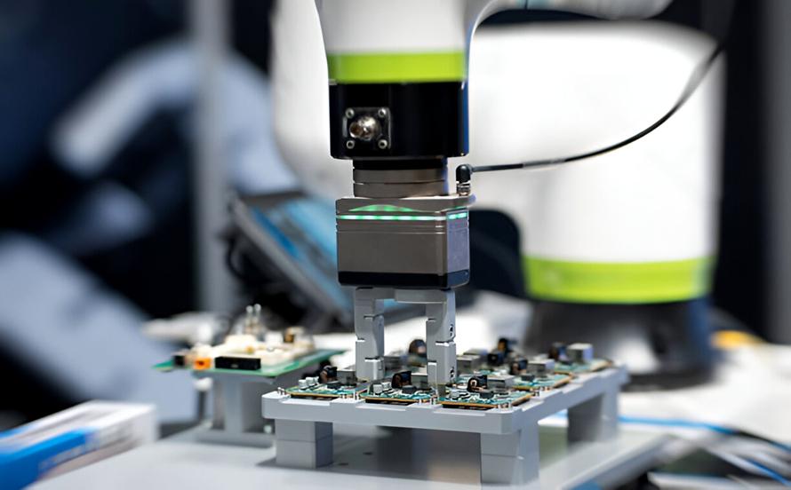
A very important process in the product development process is building prototype PCBs. It is used to validate the design before actual production, which helps in identifying design errors before actual production. It means that a good prototype assembly will necessarily be accompanied by a good protocol, which should be developed before the assembly begins and which should contain the following recommendations. If you follow these guidelines, you will have a better chance of getting the prototype PCB assembly right.
Tips for Ensuring Successful Prototype PCB Assembly
Comprehensive and Accurate Design Documentation
- Gerber Files are the Best: Success is guaranteed by using Gerber files that must include complete, accurate, and current design updates. The entire fabrication dataset, such as drill files and aperture lists, must be checked for completeness and accuracy before manufacturing begins.
- Bill of Materials (BOM) Precision: The accuracy of the BOM is key to success. It is essential to include manufacturer Spectral Pectral part numbers, component descriptions, printed dimensions, and specifications with each number of components required. It is crucial to ensure that all the components needed are in place, including the time they will be delivered to you.
- Assembly Drawings and Instructions: The documentation should include component drawings, part numbers, placement positions, polarities, and a unique set of assembly instructions. Information on critical components and assembly procedures should be explained in detail.
- Netlist Verification: To ensure that the schematic netlist is the same as the one obtained from the PCB layout, the following must be done.
Strategic Component Selection and Sourcing
- Consider Lead Times: To perform prototype runs, you should select components with quick lead times that also have ready access to stock.
- Footprint Compatibility: The footprints of every component must be synchronized with the upcoming PCB design. Prioritize your review to focus on the sizes used in packaging as well as multiple aspects regarding pin configurations.
- Component Alternatives: Determine potential replacement components in the event of shortages or unanticipated challenges.
- Reliable Suppliers: Reliable suppliers should be selected because they maintain component quality by working with trusted wholesalers and manufacturers.
- Avoid Counterfeit Parts: Customer safety against counterfeit elements can be achieved through authorized distributor purchases of vital components.
Optimize the PCB Layout for Assembly
- Design for Manufacturability (DFM): The process of Design for Manufacturability (DFM) should be implemented to simplify future assembly stages. A design that accounts for how components should be spaced should determine orientation positions, as well as soldering and product inspection accessibility.
- Panelization: Multi-prototype production becomes more efficient and cost-effective through the panelization method.
- Test Points: A design implementation of test points ensures that product testing can be done at the circuit level for debugging purposes.
- Fiducial Markers: Large reference markers should be incorporated for automated assembly equipment to precisely position components.
- Thermal Considerations: The design requires special attention to thermal management systems because they contain high-power components.
Choose the Right Assembly Partner
- Experience with Prototypes: The selection of an assembly house should focus on providers who already possess successful track records with prototype order handling.
- Quick Turnaround Capabilities: Your evaluation of their prototype delivery speed must assess their quick turnaround capabilities.
- Communication and Support: Their service should consist of straightforward information exchanges combined with reliable technical support.
- Assembly Capabilities: Check whether their assembly facilities support the precise assembly technologies, which encompass SMT, along with through-hole or mixed technology methods.
- Inspection and Testing: Verify their inspection methods, which include automated optical inspection (AOI) and in-circuit testing (ICT).
- Quality Control: A quality management system needs to be robust for quality control purposes.
Early and Frequent Communication
- Pre-Assembly Review: Prior to the commencement of manufacturing, an extensive analysis of both design files and assembly instructions should be conducted with the assembly house.
- Regular Updates: Multiple updates need to take place during the prototype PCB assembly process to respond quickly to questions or challenges encountered by the assembly team.
- Feedback Loop: Feedback mechanisms should consist of a loop structure for understanding lessons learned from prototype assembly, which will help improve upcoming design stages.
Thorough Testing and Inspection
- Visual Inspection: MVI in PCB fabrication requires a person to visually inspect products versus a reference ‘Golden Board’ or to agree on quality parameters.
- AOI (Automated Optical Inspection): The automated visual inspection known as Automated Optical Inspection (AOI) checks printed circuit board (PCB) (along with LCD and transistor) production.
- X-ray Inspection: Through PCB X-ray inspection people examine printed circuit boards without causing any harm to their structure.
- ICT (In-circuit Test): The quality control method known as In-circuit Testing (ICT) performs both defect identification and correction functions starting from the component level.
- FCT (Functional Test):. A functional test (FCT) functions as an evaluation method for finished electronic products that examine complete device functionality via multiple testing situations.
Documentation of Changes and Revisions
- Update Part Numbers: Eurocircuits follow all requirements of the RoHS regulations that aim to remove toxic substances which endanger the environment and human health.
- Procurement Approvals: The examination of climbing electronic component obsolescence and corresponding efficient solutions through proactive methods is the focus of Sourceability.
- Separate BOM and Drawings: The document provides in-depth knowledge about Autodesk Inventor Bill of Materials (BOM) functionality and its usage for Inventor users.
- Manage Final Documentation: Collect all input from the PCB manufacturing and early prototype validation procedures and incorporate it into the final documentation bundle.
Flexibility and Adaptability
- Anticipate Challenges: Prepare in advance for unanticipated problems by implementing your approach in a flexible manner.
- Iterative Design: The process of iterative design should incorporate repeated design phases, which enable prototype testing data to inform changes and improvements.
- Problem-Solving: The team should create an anticipatory solution system to solve problems that emerge during the construction or testing of hardware in the prototype PCB assembly.
Detailed Failure Analysis and Root Cause Identification
Prototypes require a deeper analysis of failure conditions to achieve development success. The success of a prototype heavily depends on the failure analysis process.
The 5 Whys approach to failure analysis assumes that asking “why” repeatedly five times will lead to discovering the actual root of the problem. When it becomes impossible to answer the question “why” further analysis is no longer needed, as the actual problem origin has been located.
The fishbone diagram works similarly to the Ishikawa method through a graphical process, where the main problem becomes the central element, with various possible reasons extending out as “fish bones.” A comprehensive assessment requires breaking causes into defined groups, such as materials, procedures, and measurements when performing examinations.
Pareto analysis is effective when all probable causes for an issue are sorted, with 80% of the possible solutions deriving from just 20% of the possible contributing factors. This method identifies and eliminates the less important causes to investigate the most critical situations. The application of this approach minimizes wasted time while identifying the most common types of mistakes in the creation process.
Conclusion
Through an extensive evaluation process, manufacturers can prevent repeating mistakes while optimizing designs for manufacturing and performance. The manufacturing transition from prototype to production receives support through this process, which works to eliminate both expensive rework and manufacturing setbacks. PCB suppliers can optimise the PCB assembly services after different PCBs are assembled. Because every prototype PCB has a unique requirement for suppliers to gain experience from the manufacturing process.


